Building the XRP Robot
Assembling the XRP robot is easy, but be sure to follow the steps here to be sure that the wiring is correct and all the pieces are added correctly to the chassis.
Below is a video provided by SparkFun Electronics showing how to assemble the robot followed by a step by step set of written instructions below.
The XRP kit (0:37)
The XRP kit contains all the parts you need to assemble and use your robot. You only need to supply 4 AA Batteries (preferably rechargeable) and a micro USB cable to connect your computer to the robot. The contents of the kit are shown to help you identify the parts during assembly.
- Robot chassis

The chassis is a single-piece design that holds all of the robot components. It is designed with a rail system that is designed to make adding additional components easy and without the need for tools. All the robot parts simply snap onto the chassis to make assembly as simple as possible. You can also 3D print your own parts to attach to the chassis.
Robot controller

The robot controller has the RP2350 microprocessor for Version 1 and the RP2040 microprocessor for the Beta version that reads the sensors inputs, runs the Python or Blockly program and drives the actuators (motors). It also has additional components to sense accelerations and headings of the robot, and communicate over WiFi with your laptop or phone.
Electronics parts
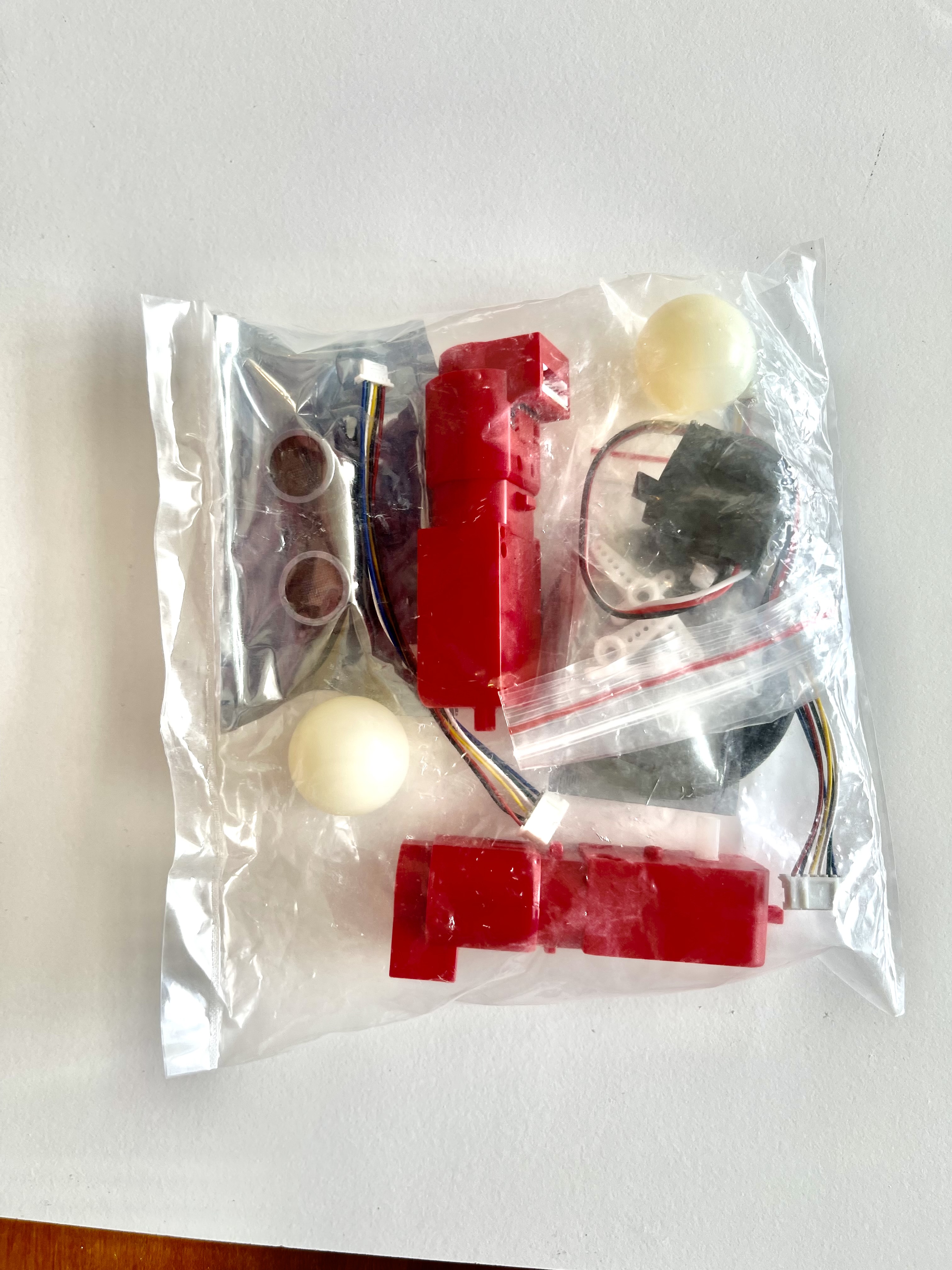
The components in the bag of elctronics parts will each be shown individually below.
Motors and cables

The motors are used to drive the robot and are attached to motor controller through the associated cables.
Battery case
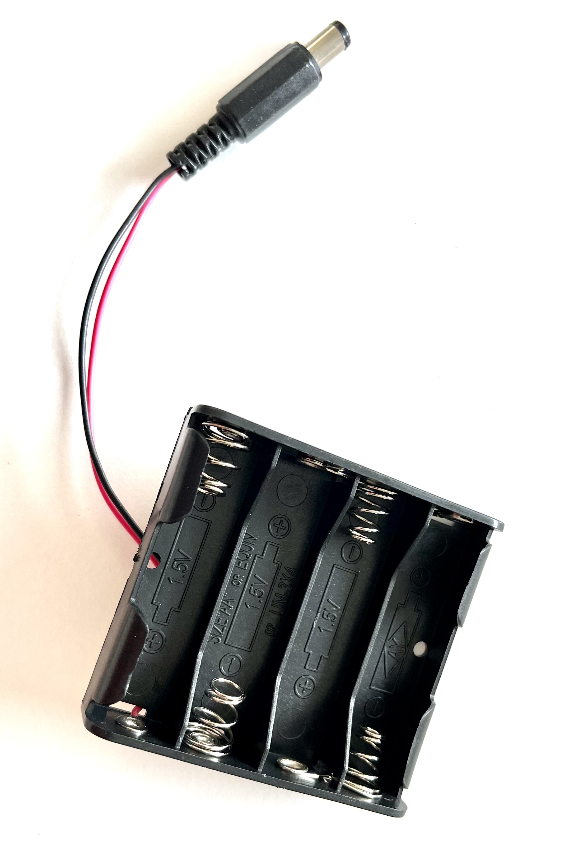
The battery case holds 4 AA batteries. You can use any standard alkaline cells but rechargeable cells are prefered so that you don’t have to keep replacing them as they run out of energy.
- Ultrasonic rangefinder

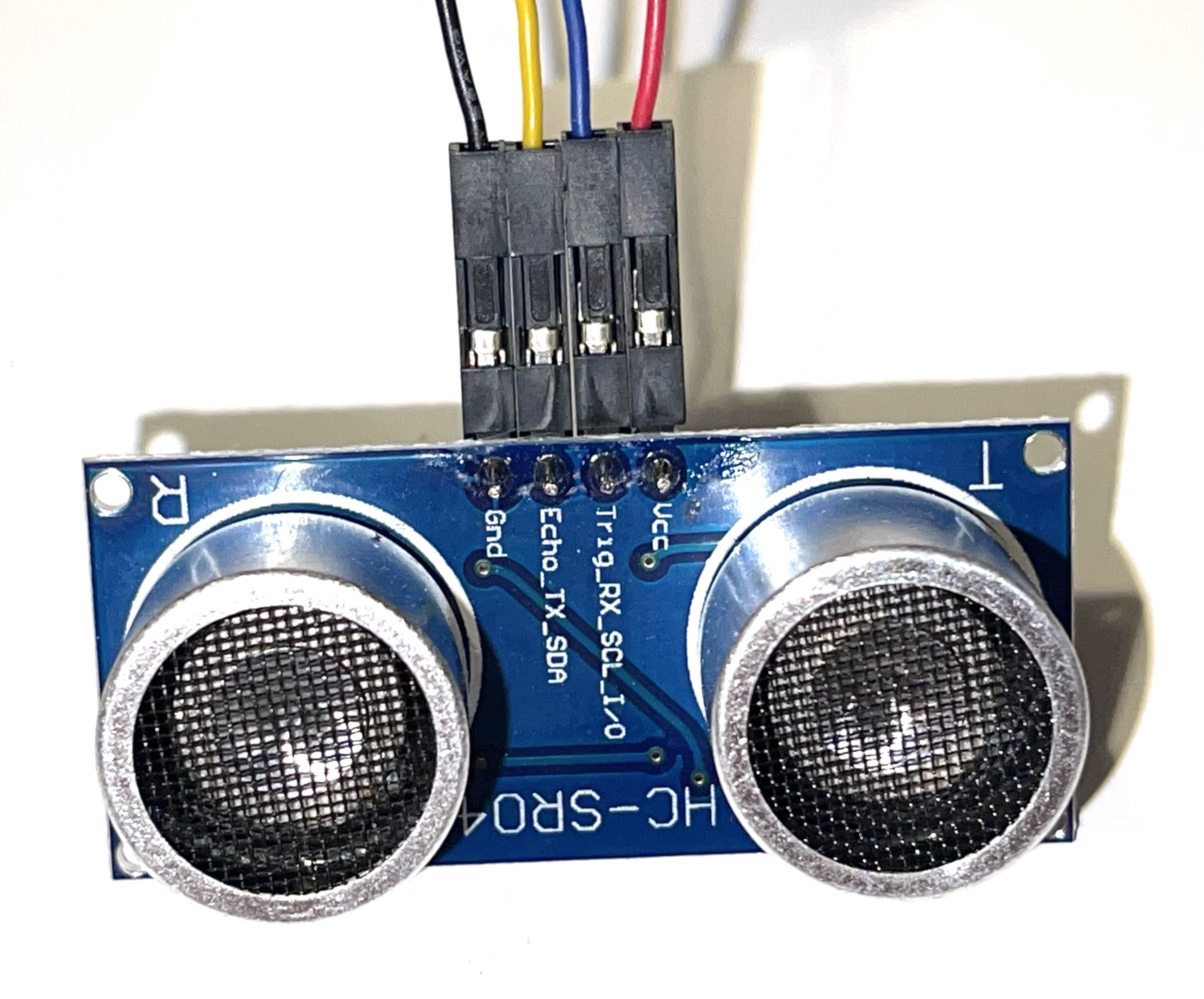
The ultrasonic wire has two power wires labeled Vcc (red wire) and Gnd (black wire). It also has two additional connections that operate the sensor and get range data. These are trig (blue wire) and echo (yellow wire). A common mistake when wiring this sensor is to get these two wired incorrectly.
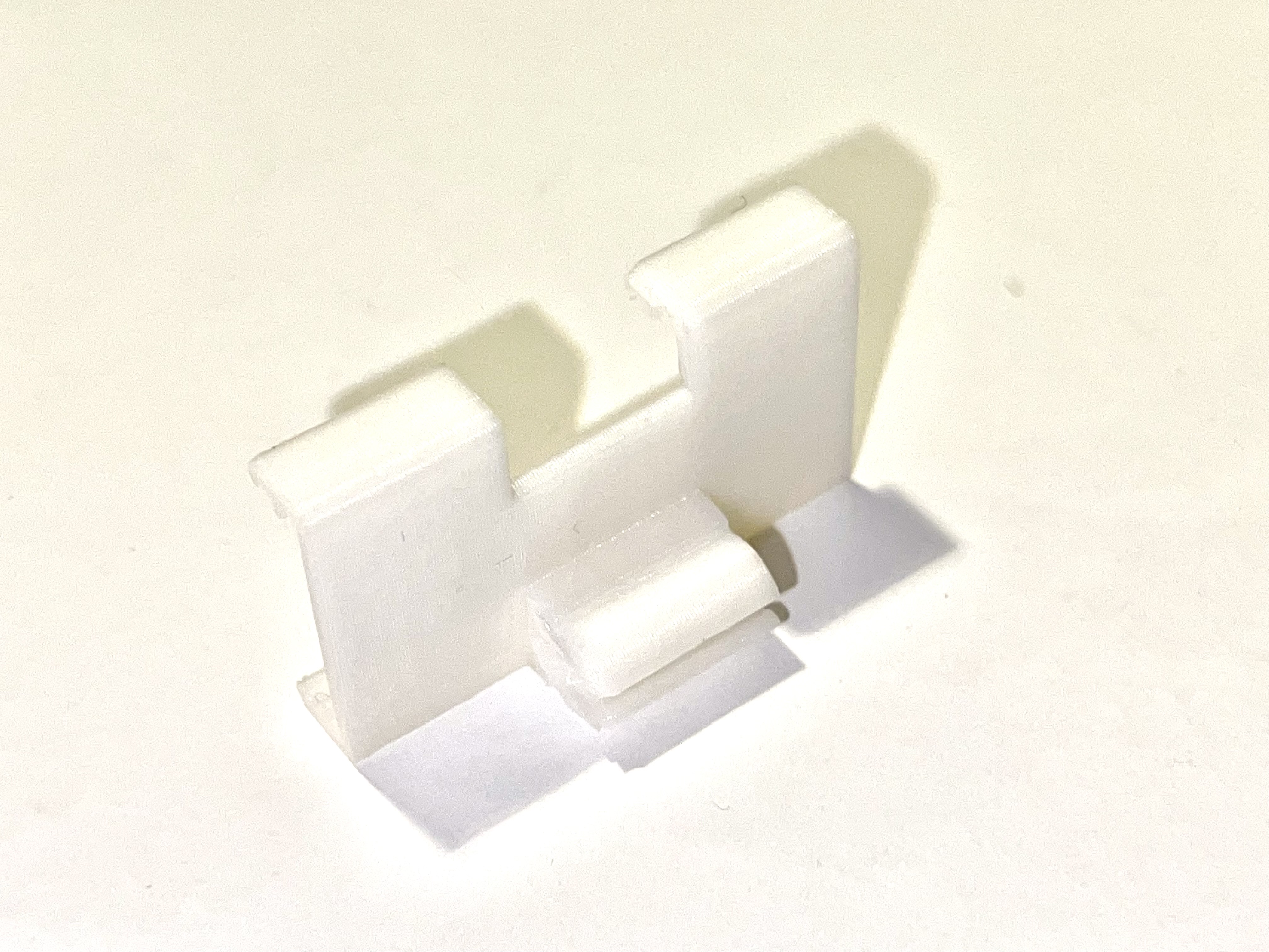
- Rangefinder bracket

- Reflectance sensor
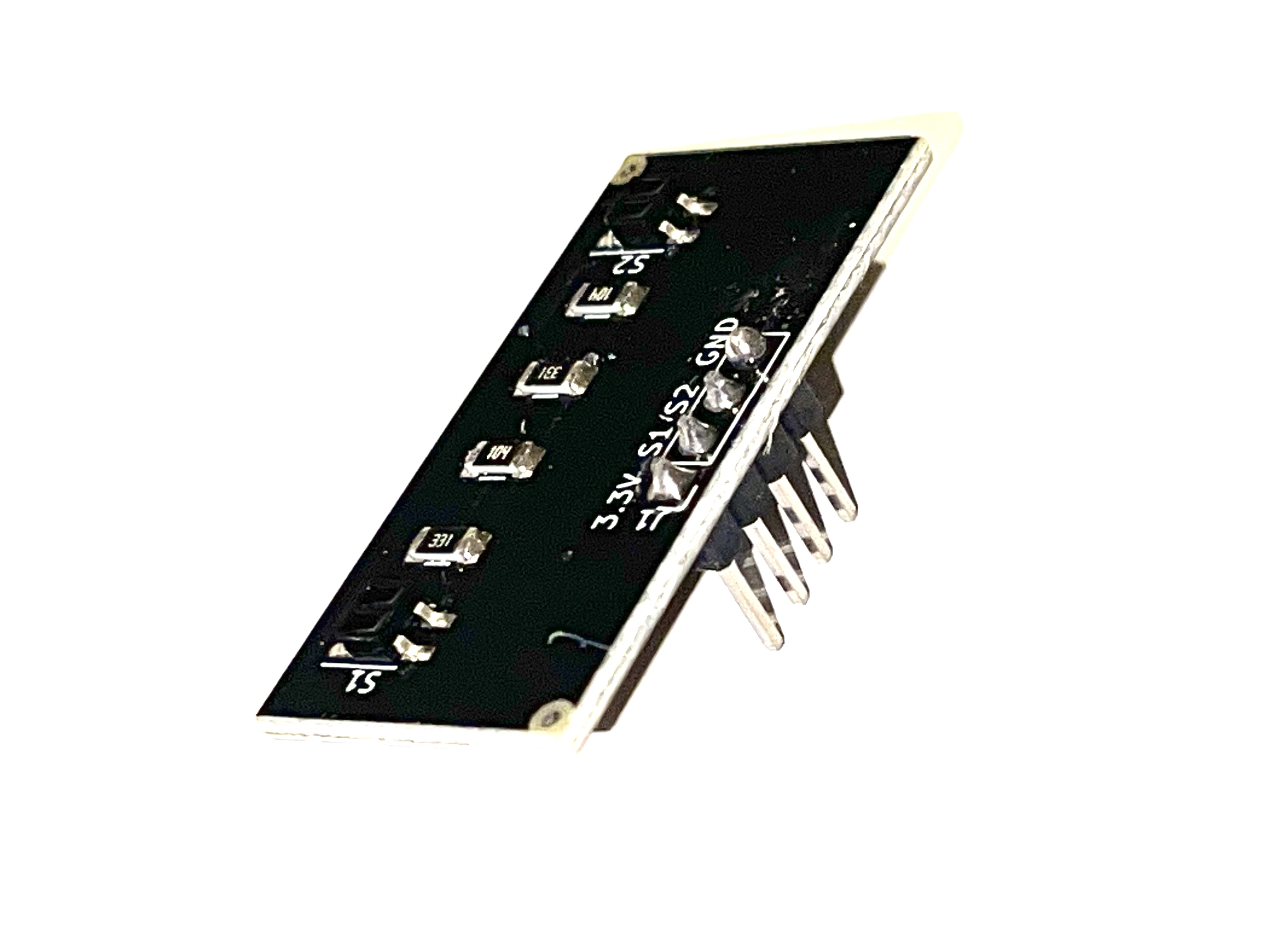
- Reflectance sensor bracket
- Sensor cables

These cables connect the rangefinder and line following sensors to the robot controller. When installing these on the sensor end, you must be careful to install the wires correctly, so be sure to carefully read the instructions when attaching them. Miswiring is the motors is the most common cause of problems when assembling the XRP robot.
- Tires (o-rings)

These o-rings are used to form tires to slip over the plastic wheels to give the robot more traction, especially on smooth surfaces.
- Servo motor

- Servo arm

- Servo bracket

The servo is a special type of motor such that when programmed with a position the shaft will automatically move to the specified angle. This is used to power the arm on your robot it can move to predetermined angles all by itself.
- Casters

The casters simply provide a low friction contact point for the front of the robot to allow the two rear drive wheels to easily steer the robot forwards, backwards, or any angle.
Assembling the XRP Robot
Assembling the XRP robot can be done without the use of tools with the optional exception of screwing the servo arm to the servo. The total process should take about 15 minutes, especially once you understand how it goes together.
Each of the following sections has a time reference for the video at the top of this page so you can see how to assemble that part. We suggest that you view the entire video before starting the assembly so you can get a good overview of how it goes together.
Inserting the robot controller into the chassis (1:18)
Nota
If you look at the connectors on the edge of the controller board labeled «Line», «extra», «qwiik», and «range» have very small pieces of tape covering the openings. Remove the tape from all four connectors before inserting the board in the chassis.
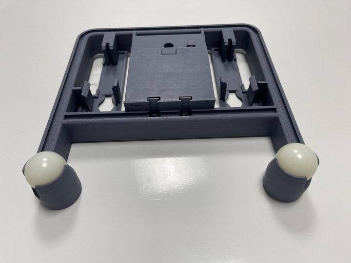
Insert the robot controller circuit board into the chassis as shown in the following picture. Observe the orientation of the board where the battery connector (5) istowards the back of the robot as shown. Also the top corners of the board are inserted part way into the corner pockets as shown at (1) and (2). The clips in the chassis (3) and (4) are designed to hold the chassis in place when it is pushed in.

Then push down and foward on the back edges of the board so that the front corners are completely seated in the pocket as shown at (1) and (2) and the board snaps down as shown at (3) and (4) in the following photograph. It might be helpful to view this part of the assembly in the video from the top of this page.

Installing the battery pack (1:39)
The battery pack is installed by:
Inserting the cable through the cutout in the battery pack area in the chassis.
Pushing the edge of the battery pack against the fingers in the chassis which hold it in place.
Push the battery pack in place into the robot chassis so that it is full seated.


Adding the battery cover (2:29)
The battery cover is very easy to install, just line up the two tabs on the battery cover with the two slots in the chassis just outside of the battery case. Then the clip snaps into place as you push the battery cover into place.


Inserting the casters into the chassis (3:06)
Install the white front casters (balls) into the chassis by pushing them into place. Once they are installed, the casters should rotate freely.
Adding the motors
The red hobby motors supplied with the kit include encoders (sensors to measure wheel rotation) to make it easy to program the robot to drive for specific distances and speeds. This will give your robots more control and accuracy as your are writing progams to operate it.
Putting the wheels onto the motors (3:22)
The wheels press fit onto the white motor shafts. Notice that the motor shafts have two flat sides that correspond to the flat edges in the center of the wheel. The wheel is pressed over the motor shaft so that the center part of the wheel that sticks out is closest to the motor body and that the wheel is pressed all the way onto the motor shaft.


Putting the tires onto the wheels (3:45)
The tires are rubber o-rings that slip into the groove on the outside rim of the wheel. Simply stretch the o-ring to get it to move into place. These will provide friction when the robot is driving, especially on smooth surfaces.

Connecting the motor cables to the motors (3:52)
The motor cables connect the motor to the robot controller so that it can drive the drive the motors and receive data from the motor encoder sensors that provide position and speed information for your robot program. This encoders all the robot to drive at a desired speed and drive for a desired distance.
The wider connector on the cable is inserted into the motor. Notice that pins (wires) on the motor connector are closer to one side than the other. Similarly, the holes on the connector attached to the cable are closer to one side.

Installing the motors into the chassis (4:09)
The motors snap into the chassis from the bottom once the wheels and cables are installed. The motor is oriented so that the wheel goes through the slot on the chassis as shown in the picture. Ideally you should push the wires from the motor through the opening in the chassis to the top of the chassis so they can be attached to the robot controller. Then seat the end of the motor opposite the cable end, then snap the wheel side of the motor into place. Repeat for both motors.


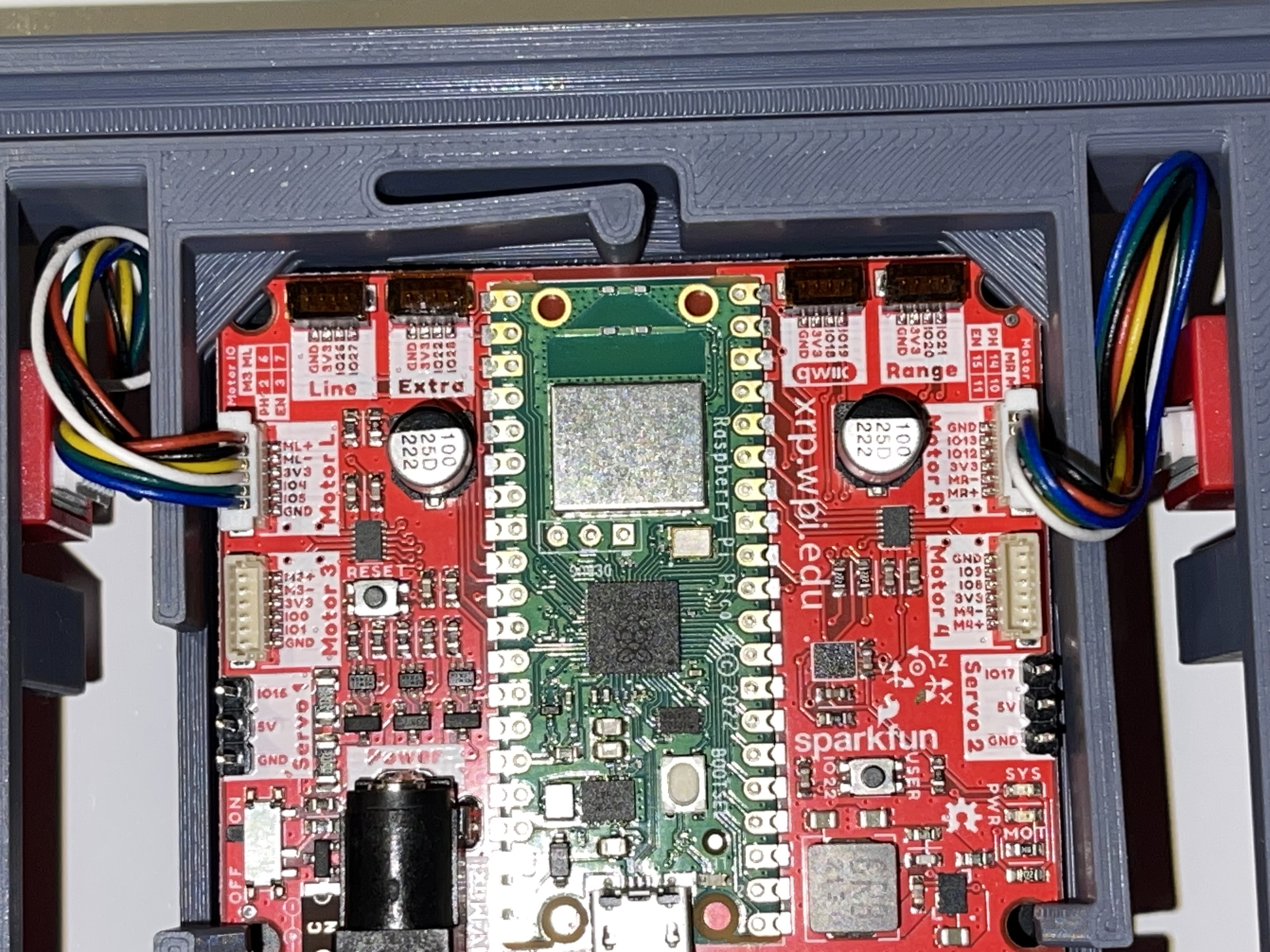
Photo of the controller board
Many of the following instructions require attaching cables to the connectors on the controller board on the robot. The printing on the board identifying the purposes of each of the connectors and the pins is very small to fit on the small board. To make assembly easier, refer to the following photograph of the board if needed.

Connecting the motor cables to the robot controller (4:43)
The motor cables are connected to the white connectors on the side of the chassis labeled Motor L and Motor R for the left and right motor cables.

Adding the Sensors
The line following sensor can detect lines on the driving surface that have a different reflectivity. These are typically used in robot applications to follow lines or locating interesting places on a board or mat. It has two pairs of LEDs and photo sensors to emit infrared light and measure the reflected brightness.
The ultrasonic rangefinder uses sound to measure the distance to objects in front of the sensor. An ultrasonic (inaudible high frequency) short sound is sent from one of the transducers which is reflected back by nearby objects and received by the second transducer. The time of the sound round-trip is measured to determine distance to nearby objects.
Wiring the sensors (5:11)
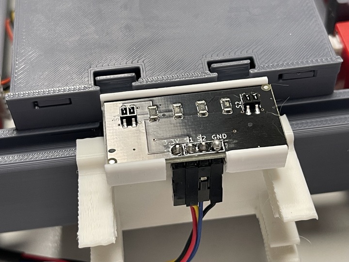
The sensor cable is connected to the line following (reflectance) sensor as shown in the picture below. Be sure to observe the order and color of the wires connecting to the sensor. The connectors simply push over the sensor pins. Be sure that they are fully seated as shown in the picture and video to ensure a good connection.

The rangefinder is wired by attaching the four wires from the sensor cable to the pins on the rangefinder as shown in the picture below. Be sure to connect the wires to the pins in the right order.
Attaching the brackets to the chassis (5:44)
The rangefinder bracket is attached to the front of the chassis just above the reflectance sensor as shown in the picture below.

The reflectance sensor bracket is installed on the chassis as shown in the picture below. The ball end of the bracket is inserted into the slot in the front rail.

Inserting the line follower into the bracket (6:19)
The reflectance sensor is inserted into the bracket as shown in the picture below. Also look at the side view of the assembly to see how the sensor is correctly positioned in the bracket.

Attaching the rangefinder to the bracket (6:38)
Attach the rangefinder to the bracket as shown in the picture below.

Connecting the cables for the line follower and rangefinder (6:55)
The cables from the reflectance sensor (line follower) and the rangefinder are connected to the connectors on the controller board. Notice that there are labels on the board for each of these cables to help you get them into the right connectors. The line follower cable goes into the connector labeled Line and the rangefinder goes into the connector labeled Range. It is a good idea to put a small loop in the wire that can be tucked into the chassis before connecting it to help keep the wiring neat and less likely to get snagged.


Attaching the servo
The servo is used to rotate the arm to the desired position. It has the advantage over a normal motor in that it has sensors inside of it to allow it to move to a desired position that you can program.
Attaching the servo bracket to the robot chassis (7:29)
The servo is attached to the robot by first inserting the ball end of the bracket into the upper slot on the back rail, then snapping the bottom part of the bracket over the bottom part of the rail.


Mounting the servo to the servo bracket (7:54)
The servo snaps into the servo bracket as shown in the photo below.

Connecting the servo cable to the robot controller (8:06)
The servo cable is connected to the slot labeled Servo 1 on the robot controller board as shown in the photo below. Be sure to connect it as shown with the black wire connecting to the Gnd terminal on the Robot Controller board.

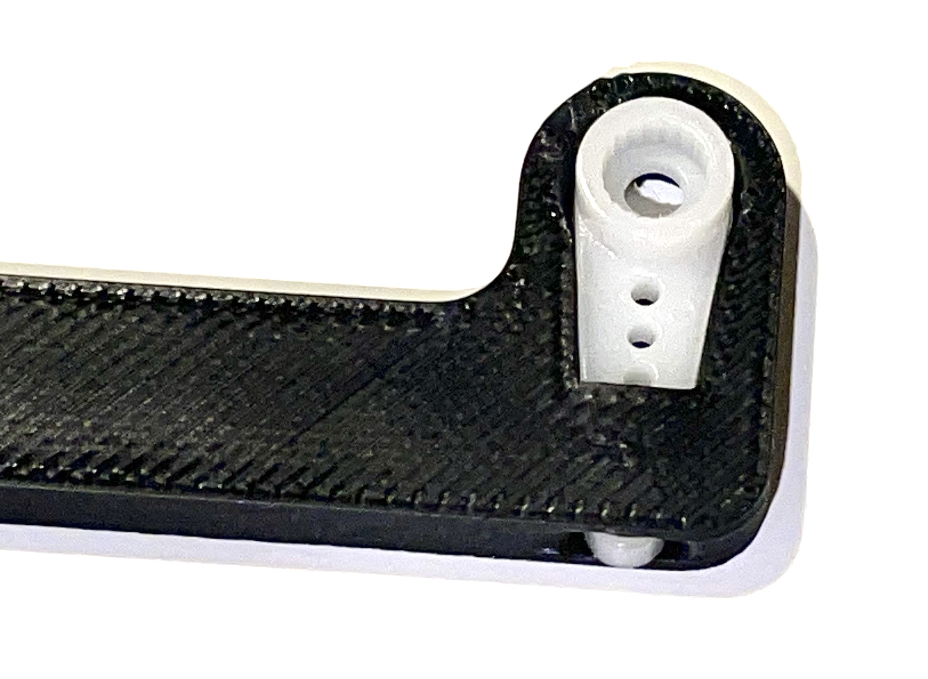
Inserting the servo horn into the robot arm (8:27)
The servo horn is the small white plastic arm that attaches to the servo by pressing onto the servo shaft. There are several servo horns that come with the servo accessories. The one that you should use has a hole for attaching to the servo shaft at one end, and a small arm at the other end. It gets installed into the slot at the end of the larger black servo arm as shown in the picture below and the video. Be sure to install the servo arm so that it is oriented as shown in the photo, in particular make sure that the mounting flange is facing the correct direction.
Mounting the arm to the servo (8:45)
The servo arm simply presses onto the white shaft on the servo. The servo shaft only has about 180 degrees of rotation so it’s important to install the arm so that it can move through its full range of motion while mounted on the robot. Holding the servo so that it’s flat with the wires coming out to the left, the arm should be mounted so that it has 180 degrees of motion from front to back. That is the arm will never travel below the level of the servo body. You can see how this is done by looking at the video at the indicated time stamp. This image shows the servo at the end of its travel inside the robot chassis. The other end of the travel will be slightly below horizontal behind the robot.

Initializing and testing your XRP (10:21)
Refer to SparkFun’s video at the top of this page to set up your XRP and ensure that it’s working correctly!
Once your XRP is connected, skip to (12:44) in the video and follow along with the built-in test to ensure that the sensors and motors are working properly.
Troubleshooting the robot build
Generally the build of the robot is very strightforward, but from feedback we have compiled this section that describes some of the common issues we have seen as people are building the XRP.
Rangefinder or the line following sensors don’t work in the Installation Verification Test
It is very easy to accidentally attach the rangefinder and line following sensor cables to the wrong connectors on the controller board. Be sure to verify that the rangefinder is in the connector marked «Range» and the line following sensor is in the connector marked «Line».
If the connectors are reversed and you have to remove them, be sure to only remove the connector by pulling on the plastic shell. Do not pull on the wires as you might accidently pull them out of the connector.